
 Japanese Self Defence Naval Force Guided Missile Destroyers built 1983-86, active until 2021 (DDG-171-172).
The The Hatakaze-class were the 3rd generation of guided-missile destroyers in the Japan Maritime Self-Defense Force (JMSDF) and with gas-turbine propulsion. They repeated the missile and armament suite of the Tachikaze class, but had improvements in all areas. The most important is that like the Shrirane class DDH, these large ships were intended to work as group flagship. With tjheir extensive communication suite and accomodations, they could indeed replace a dedicated command ship in case of absence due to repairs, accident, or battle damage. Critical to this role was also their OYQ-4-1 type tactical control system able to coordinate all ships in the vicinity for a coordinated defense. They featured the latest SM-1MR Standard missile surface-to-air missile, and the usual ASROC plus one of two Type 42 5-in/54 caliber main gun all on their long foredeck, but also featured canisters with the RGM-84 Harpoon, Mark 15 20 mm CIWS, triple acoustic torpedo mounts but lacked an helicopter (still they had an helideck). That’s when their TDS took all its importance as this capital ASW capability was delegated to the specialists present. Only two ships were built and completed in 1986-88, active until 2020-21. They are now a bit forgotten now, eclipsed by their famous successors, the Kongō-class (1991), first Japanese AEGIS destroyers, albeit JS Shimakaze is still active as a training ship today (2026) at Kure, probably one of the oldest active warship in the Fleet Surface Force (Japan Maritime Self-Defense Force).

Development
The Japan Maritime Self-Defense Force (JMSDF) initiated the procurement of guided-missile destroyers (DDG) with the Amatsukaze (35DDG), 1st Defense Build-up Plan, which were followed by three Tachikaze-class (46/48/53DDG), half the “8-ship, 8-aircraft” formation planned for Escort Flotillas all for the Mid-Term Defense Program (FY1978–1982). These designed were loosely modeled after the U.S. Navy’s Charles F. Adams-class, first USN DDGs, with a Tartar missile system at the stern, so with a restricted firing arc. This limitation could be mitigated by maneuvering but in general it was seen as more beneficial to have these at the bow. The third Tachikaze-class ship, Sawakaze (53DDG) which was to inaugurate gas turbine engines ended with conventional steam turbines because no large enough gas turbine was then available.

Under the FY1978–1982 Mid-Term Defense Program, construction of four DDGs was considered to reach the planned “8-ship(Helicopter less DDGs), 8-aircraft(Helicopter ships)” structure and these were intended to be new-generation with a bow-mounted Tartar and gas turbine propulsion. However the JMSDF still could not assess in real life the feasibility of adopting gas turbine main engines, on top of budgetary constraints, so for that year’s program this was reduced to just one ship, the remaining three deferred to the FY1981–1985 Mid-Term Defense Program. FY1981–1985 program thus was to count two of the planned destroyers only, in the no-helicopter category, but with gas turbines and bow missile systems. The third originally scheduled for FY1985 was eventually cancelled, replaced with a conventional destroyer (DD) due to the likelihood of the Aegis system to be released to Japan and planned swap to costlier but infintely more capable Aegis ships.
Design of Hatakaze class
Hull and general design

Hatakaze class profile, shipbucket’s colossum and hood via the blueprints.com
In terms of design, this class shared many features with the Asagiri class (58DD) and like them grouped the main armament on a long forecastle and continuous/flush deck with a distinctive knuckle at the bow, also adopted by US ships of the Leahy and Belknap class ocean escort(cruisers). The hull measured 150 m (492 ft 2 in) overall, 143 meters between parallel, for a beam of 16.4 m (53 ft 10 in) and draft 4.8 m (15 ft 9 in) showing the increased dimensions of modern destroyers. Displacemment was moderate still at 4,600 long tons (4,674 t) standard and 6,000 long tons (6,096 t) full load for Hatakaze, while her sister was 50t heavier at 4,650 long tons (4,725 t) standard and 6,050 long tons (6,147 t) full load.
Widers ships due to Gas Turbines
The new ships had a length-to-beam (L/B) ratio of 9.1, a wider hull similar to that of the Haruna class (43/45DDH) however versus the Tachikaze’s 1/10 ratio and Asagiri’s 9.4/10. Stability was requirted indeed to composante for a new, higher the center of gravity due to the adoption of lighter, compact gas turbine engines instead of traditional steam turbines and associated boilers, twice as much heavier. There was to be also an increase in onboard equipment with the CIWS and antiship missiles placed high up from the start, as well as the new command facilities and extra communication suite. The sheer of the bow was minimal, and the bulwarks were a novelty. Loading and unloading missiles via the missile launcher required stability indeed, as well as demanded the best possible seaworthiness.
Helideck and Stability
 Planned under the planned under the “8-ship, 8-helicopter” formation the aft deck was configured as a helicopter flight deck (helideck) but no hangar was planned to gain space, so none of the two ships had a permanently assigned helicopter. This was a crucial lack in ASW capabilities, but the occasional presence of an helicopter was to be used mostly for liaison in the fleet when used as flagship, not for ASW work anyway. The deck length was reduced under normal conditions, so aft main gun had its is rotated 90 degrees sideways to secure takeoff and landing operations. For better safety this class was equipped with fin stabilizers of a new, betetr type. He sister, Shimakaze, adopted the new AC-14 type anchor—capable system of the Asagiri class (58DD) for extra stability for helicopter landings.
General Layout
Externally, these ships as seen above were characteristic of Japanese late designs under USN design influence: The clipper, streight bow with an axial anchor was followed by bulwarks, protecting the long and sloped upwards foredeck, with knuckles in the bow for better seakeeping as seen above. The main weaponry was located there, in order, the SM-1 Standard SAM system (single arm though), “A” Type 42 main gun position on a raised structure to clear out the SM-1 launcher ahead (and ASROC aft) followed by the latter ASROC luncher, and its automated rload system at the base of the bridge. The latter was the same old three-tiered structure with short wings, three levels, and two raised fire control radars for the SM-1 followed by a an upper communication room, framed by a tall lattice mainmast carrying the main aerial radars. Pas the structure, which ended well past the amidship section was the blocky funnel with rounded edged, and two upper exhausts with heat radiation reduction systems.

It also supported maincommunication antennae. Immediately behind on a platform were located the two quad Harpoon launchers firing corssed inwards. Pas this was the rear structure block, with the aft fire direction radar and a lattice for the secondary aerial, platforms for the two CIWS, only able to defend a side each, and the two motor cutters. Six containerized life rafts were grouped on the structure, abaft the mainmast. The “B” main gun was located on deck just forward of the helideck which ended over a cutout in the hull deck, hosting part of the ASW suite and able to deploy inflatable boats. Overall, still a balanced outlook, with a bridge amidship due to the long foredeck. They had a crew of 260 total, not a lot for such large hull, partly tanks to automation.

Internal organization and Accomodations
The open deck above the bridge was called the “03 Deck” the bridge itself “02 Deck”. The deck extended from the anchor deck to the aft helicopter deck as “1st Deck” and the 2nd Deck at the first level within the hull comprised the steering room, mess hall, and galley. Crew quarters were distributed throughout the hull. They were roomy spaces making the ships popular for the crews, with “only” two-tier bunks for officers and three-tier bunks for enlisted personnel in smaller, bettr noise insulated rooms. The galley and enlisted personal mess deck were located amidships, slightly aft of the funnel. The galley had four steam-heated cooking kettles. Still, spatial constraints had the enlisted mess deck L-shaped, large enough still for 60 personnel, for a meal at one time. Due to quarters it worked 24/7 with rotating personal, albeit of course night quarters were reduced. The machinery control room included the damage control station amidships. The four main gas turbine engines and four generators were still dependent of bridge instructions. The Hatakaze class remained strictly indirect, without direct control from the bridge possible (remote engine operations).
Powerplant
 Speaking of gas turbines, this class was the first in Japan for pure guided-missile destroyers (not general purpose) to adopt gas turbines as a main propulsion system. Rolls-Royce Spey had been installed on JDS Asagiri and sisters of the 58DD class. For the Hatsuyuki class (52DD) like this class, a COGAG (Combined Gas turbine and Gas turbine) arrangement was adopted with Spey SM1A and Rolls-Royce Olympus TM3B for a high/low speed mix. The latter had 36,000 horsepower per shaft. This COGAG configuration combined different gas turbines for better flexibility and range without loosing raw power and accelration. On the Hatakaze class, a maximul speed of 30 knots was setup as the ‘minimum acceptable level’ for operations, a reduction compared to 32 knots for the Tachikaze class however. Hull dimension constraints forbade a stagerred arrangement in the engine roomas the steam-turbine Tachikaze class and instead, they had a less secured parallel arrangement like for the Hatsuyuki class.
The four gas-turbine so were a high/low mix of two Kawasaki Rolls-Royce Spey SM1A gas turbines (26,650 hp combined) for cruising and two Rolls-Royce Olympus gas turbines (49,400 hp combined) for high speed only. Globally they provided 72,000 hp (54,000 kW) on 2 shafts for a top speed of 30 knots (56 km/h; 35 mph) and a range of 6,000 nm at 20 according to some sources. No figure available for own many gas turbine oil they carried (in the US this was the same as avgas, JP-5).
Radical Noise Reduction
However what the Hatakaze did, was to adopt comprehensive measures for the first time to reduce underwater radiated noise from the propulsion system. Not, in popular belief to make the ships more difficult to detect for submarines, but just to reduce parasite noise when using ASW passive detection systems.
This consisted in the following:
-Vibration-isolating mounts for the main engines, auxiliary machinery, reduction gears
-Vibration isolation for major piping
-Vibration-damping materials
-Vibration-isolating joints
-“Hull Masker” and “Prairie” systems already present on the Shirane class (50/52DDH).
Increased Electric Power
For global electrical power, there were two gas-turbine generators and two diesel-driven main generators (each 1,200 kW) installed in the No. 1 and No. 3 machinery rooms. Extra power was needed for extra systems, future upgrades, and all the extra communication suite for flagship duties.
There were diesel emergency generators (300 kW) distributed at the forward and aft sections of the third deck for redundancy.
The main gas turbine generators were Kawasaki Heavy Industries M1A-05, upgraded version of the M1A-02 used in earlier destroyers.
Protection
Passive
Albeit there are no details for this, we can assume the “usual suspects”: Bulkheads to stop flooding between the three machine rooms, two more separating the forward and aft section, plus a double bottom running all the lenght but to the start of the sonar section forward and elevated under-keel to the shaft levels. There was likely extra protection for the ammunition magazine, extra plating aroud the “boxes” they formed, plus internal rapid-flooding cocks. There was the redundancy of the power supply as well in case of a hit disabling either of the turbines. Same for fire protection, there were min fire control stations across the ship, spinklers with detectors in the ammuunition and machinery rooms and for the crew halon fire extinguiser posts in living quarters and at many places across decks. There was also an NBC protection with external detectors or all NBC threats, full sealing of all external doors and hatches and overpressure by the air conditioner, a feature well appreciated anyway given the wide diferences of climates and temperatures from the north of Hokkaido to the southernmost islands close to Taiwan in the Japanese extensive EEZ.
Active
It consists in four systems, in addition to the CIWS:
NOLR-6C intercept
: An electronic support measures system used in the Japanese Navy since a decade and incrementally improved. From the outset, the NOLR-6 series Electronic Support Measures (ESM) system installed featured built-in connectivity for ECM from the beginning but not the new OLT-3 system, not fitted until the 54DD class albeit it was retrofitted to earlier ships in the class. Additionally, the ESM system upgraded to the NOLR-6C separating signal analysis and direction-finding functions.
OLT-3 jammer: The latest in electronic jamming systems, from Hitachi and other providers, retofitted latter as seen above.
Mark 36 SRBOC:
The classic US and allied standard decoy launcher system, using standard 5-inches rockets of all types, remotelly launched. Two installations. They fired the OLR-9 missile warning system (RWR) and Mk.36 Mod.6 SRBOC. The two Mk.137 were six-cell decoy launchers for anti-missile soft-kill capability.
Type 3 Towed torpedo decoys:
It was a dometic variant of the US Fanfare (T Mk.6) towed decoy installed for torpedo defense and launched from the stern.
Armament

The weapon suite is essentially the same as on the Sawakaze class (DDG-53) but with the SAM and CIC systems having half the capability of the California-class nuclear-powered guided-missile cruisers. Still this class was considered the pinnacle of conventional (pre-Aegis) guided-missile destroyers in Japan. They were very capable ships for the 1980s late still. The primary weapon for this class was called in Japan back then the “Tartar-D system”, with subsystems identical to those of the Sawakaze (53DDG) with the Mk.74 Mod.13 Guided Missile Fire Control System (GMFCS), Mk.13 Mod.4 Guided Missile Launching System (GMLS), and RIM-66B/E Standard MR (SM-1MR) surface-to-air missile (SAM). The forward quadrant led to the placement of this system on the bow deck and the two GMFCS units on the forward superstructure.
Consideration was given after commissioning adding the SM-2MR operational capability with similar modernization upgrades similar to the New Threat Upgrade (NTU) going in U.S. Navy but these plans were ultimately shelved in favor of the Aegis destroyers. The Mk.13 single launcher forward used for the Standard could be used to launch the Harpoon, but the magazine capacity available for SM-1MRs for this class adopted a different approach like on the Asagiri class with instead two quadruple Harpoon launchers installed on the 01 deck, aft of the funnel port and starboard. This avoided bottlenecks in firepower when the SM-1 was used suddenly against both aerial and sea targets. At least the eight Harpoon were independently available at all times.
The gun main armament comprised two of the Type 73 5-inch/54-caliber rapid-fire gun, forward on a deckhouse the other on the aft deck and working with the Type 81 Fire Control System Model 22 (FCS-2-22) on the bridge structure. And there were the two Close-In Weapon Systems (CIWS) mounted on the port and starboard sides of the aft superstructure. The Type 74 ASROC immediately aft of the forward gun turret was unchanged, and could be reloaded twice with its new direct-loading system from the magazine introduced with the Hatsuyuki class, thus it was closer to the bridge structure, with a slanted loading hatch on the bridge front face. The secondary, closer ASW system was a pair of the usual Triple 324mm torpedo tubes on the upper deck both sides, beneath the Harpoon launchers. The underwater attack fire-control syste was the SFCS-6 as on the Sawakaze, Hatsuyuki, and Asagiri classes.
C4I: OYQ-4-1 TDPS
The tactical data was the top of it all: This processing system was at the core of the combat system, pre-aergis excellence. The OYQ-4-1 was an upgraded version of the OYQ-4 on Sawakaze. Its computing suite consisted of two AN/UYK-7 units, and the TDS console arrangement included one large OJ-197/UYA-4, nine standard OJ-194B/UYA-4 units which was exceptionally robust as a configuration for a Tartar/SM-1 ship. This setup necessitated led to a significant expansion of the Combat Information Center (CIC) and associated equipment rooms as well as greater air-conditioning facilities compared to the Tachikaze class. The wider hull allowed this and the internal placement for the CIC was standard as with the Hatsuyuki class.
SMI-1MR SAM
 The RIM-66 Standard Missile-1 Medium Range (SM-1MR) is a naval surface-to-air missile originally developed by the United States to replace the older RIM-24 Tartar missile. Because it was engineered as a direct replacement, the SM-1MR was designed to be fully backward-compatible with existing Mk 74 Tartar fire-control systems and Mk 13 single-arm launchers. The Japan Maritime Self-Defense Force (JMSDF) heavily adopted the Tartar and subsequent SM-1MR weapon systems across several generations of its guided-missile destroyers (DDGs):
-Tachikaze-class Destroyers (Tachikaze, Asakaze, Sawakaze). Originally built with the Tartar system and later upgraded to deploy the SM-1MR.
-Hatakaze-class Destroyers: (Hatakaze, Shimakaze) Built specifically to utilize the SM-1MR utilizing the Mk 13 launcher paired with Tartar fire-control radars.
SM-1MR (Tartar Replacement) specs: Medium-range fleet air defense against anti-ship missiles and aircraft.
Guidance: Semi-active radar homing (homing in on radar energy reflected off the target by the ship’s Tartar fire-control directors).
Range: Approximately 25 to 35 nautical miles (46 to 65 km).
Propulsion: Dual-thrust solid-fuel rocket motor.
While the U.S. Navy officially retired the SM-1MR from active service in 2003 in favor of the newer Aegis-compatible SM-2MR, the system served as the backbone of Japanese regional air defense for decades until it was phased out by Aegis-equipped destroyers (like the Kongo and Atago classes) firing newer Standard Missile variants.
5-in/54 Mark 42 (N°51, 52) Main Guns
 When a Japanese destroyer carries multiple American-designed 5-inch/54-caliber Mark 42 main guns, the mounts are numbered sequentially from bow to stern. Therefore, Mount No. 51 is the gun located on the bow (Position “A” or “X”), while a subsequent aft gun would be designated Mount No. 52.The Mk 42 Gun System in Japanese Service. The 5-inch/54 Mark 42 was the backbone of Cold War-era naval gunfire for both the U.S. Navy and the JMSDF. Introduced in the 1950s as a high-rate-of-fire, dual-purpose weapon, it was designed to engage both surface vessels and fast-moving jet aircraft.
Calibre: 5 inches (127 mm) bore, with a barrel length of 54 calibres (270 inches / 6.9 metres).
Rate of Fire: Originally capable of an intense 40 rounds per minute via dual automatic ammunition drums. Due to high mechanical wear and maintenance demands, the JMSDF (following the USN) down-rated them to 28 rounds per minute for better reliability.
Maximum Range: Approximately 25,900 yards (23.7 km) against surface targets at 45° elevation, with an anti-aircraft ceiling of 51,600 feet (15.7 km) at 85° elevation.
Mount Weight: A heavy, robust system weighing roughly 60.4 long tons.
Visual and Functional Characteristics: In JMSDF service, these mounts evolved noticeably over time: The “Frog-Eye” Domes: Early variants featured two prominent plexiglass bubbles on top of the gunhouse for local manual tracking (the right for anti-aircraft and the left for surface targets). As aircraft speeds increased, manual tracking became obsolete; the JMSDF eventually removed these domes on later modifications.
Shell Catching Baskets: A unique visual trait often seen on Japanese Mark 42 mounts is a large structural mesh basket rigged to the front or side of the turret. This basket was designed to catch heavy spent brass cartridge cases as they were forcefully ejected from the front of the mount, preventing deck damage or tripping hazards for the crew.
The Mk 42 Mount No. 51 was prominently featured on several classic Japanese destroyer classes, including:Tachikaze-class guided-missile destroyers (DDG), Hatakaze-class guided-missile destroyers (DDG) and Haruna-class and Shirane-class helicopter destroyers (DDH), which carried two distinct Mark 42 mounts on the bow (No. 51 and No. 52) to leave the stern clear for flight operations.
Harpoon SSM
 One of the defining characteristics of this class was the addition of long-range anti-surface strike capability. The Harpoon ship-to-ship missiles were introduced concurrently with the Ishikari-class frigates, part of the FY1977 procurement plan. These were standard US Block I housed in two quadruple Mk.141 launchers mounted amidships, beside the funnel, controlled by the SWG-1 HSCLCS fire-control system.
Weight 1,500–1,523 lb (680–691 kg) with booster. Length: 15.2 ft (4.6 m), diameter 13.5 in (34.3 cm), wingspan: 3 ft (0.91 m).
Performance: 67-70 nmi (124 km), 150 nmi (278 km) depending on launch altitude and configuration.
Speed High subsonic Mach 0.85 (855 km/h), 488 lb (221 kg) penetration high-explosive blast fragmentation warhead.
Propulsion: Teledyne J402 turbojet engine (sustainer) +booster
ASROC
 For active anti-submarine warfare in immediate vicinity, the 8-cell ASROC launcher (Type 74) or Mk.112 (J) Mod.2N was positioned immediately forward of the bridge. The ASROC launcher has a direct-loading mechanism feeding missiles from a magazine located beneath the bridge structure. For safety there were circular blow-out hatches on the side walls of the bridge in case of an ammunition magazine explosion. The RUR-5 are similar to their US counterparts: 1,073 pounds (487 kg) for 14.75 ft (4.50 m) long, 16.6 inches (420 mm) in diameter and wingspan of 26+7/8 inches (680 mm) and carrying a Mark 46 torpedo, with 96.8 pounds (43.9 kg) of PBXN-103 HE. It is powered by a Solid propellant rocket motor for a max range of 6 mi (9.7 km), subsonic.

ASROC rocket on display, open day 2017 december at Hanshin base, JDS Shimakaze
324mm HOS-301 type 68 ASW TT
 Classic US licenced triple torpedo tubes for the acoustic torpedo installed on both sides amidships. The HOS-301 could be reloaded by hand. The Mark 46 torpedo, also used by the ASROC system is powered by a 2-speed, reciprocating external combustion using Otto fuel II to 12,000 yd (11,000 m) and at a max. depth of 1,200 ft (370 m), top speed 40 kn (74 km/h; 46 mph) and using Active or passive/active acoustic homing. The warhead, as seen above, is the 96.8 pounds (43.9 kg) of PBXN-103 HE. They were modified for cold-weather operations and to adjust the center of gravity, later upgraded to the HOS-301(D) specification, which supported Mk.46 torpedoes.
The underwater attack fire-control system for these was the SFCS-6A for the early 9 ships, based on the Shirane-class system but with an inter-computer link to the Tactical Data System (TDS) and SFCS-6B for the last three ships in class, which had fire-control capabilities for the new Mk.46 torpedo. The SFCS-6A systems on early ships were retrofitted to the SFCS-6A-1 standard, so that they could also control the new Mk.46 torpedo FY1985-1994.
20mm Vulcan-Phalanx CIWS
 Fitted aft either side on both ships. So theuy protected starboard and port quarters on full, but cross fire was impossible. They could fire however in concert on targets dead ahead or dead stern. The six fully automated barrels gatling 20mm/76 Mk 15 Phalanx CIWS were installed high-up in the amidship structure for a potential cross-fire and have in some angles, the two firing on the same incoming targets. Each weights 12,500 lb (5,700 kg) for a barrel length of 59.8 in (1,520 mm) for the L76 gun (Block 0), height of 15.5 ft (4.7 m). They fired a 20×102 mm tungsten armor-piercing discarding sabot (CIWS) or high-explosive incendiary tracer (C-RAM) 20 mm (0.79 in) in diameter, across 6-barrel with progressive RH parabolic twist, 9 grooves up to +80° elevation ad -6° depression on Block 0. Later blocks were modified to asymetric surface warfare, with a −20° and layer −25° depression. Their Rate of fire is legendary at 4,500 rounds/minute (75 rounds/second) for a muzzle velocity of 3,600 ft/s (1,100 m/s) and range of 1,625 yd (1,486 m) max. effective but on paper up to 6,000 yd (5,500 m). Before chaffs and EW and after the sea sparrow (which have an anti-missile vapacity) and the 5-in rounds they are the last line of active defence.
Sensors
The 3D radar in this class was the AN/SPS-52C, same as on the Sawakaze class.
The original configuration seen on the previous Tachikaze (46DDG) coupled the OYQ-1 TDS with AN/SPS-52B and resulted in manual target data entry and semi-automatic tracking. The new coupling on the Hatakazee enabled automatic detection and tracking, a marked improvement in tracking capability. The system could engage multiple air targets at once, now only limited by the rate of fire of the SM-1 SAM (single arm).
Next was the OPS-11C air-search radar mounted atop the aft mast, and OPS-28 surface-search radar mounted atop the forward mast.
The OPS-11 was initially planned for a higher position forward but ended relocated to a newly constructed aft mast to avoid interference from gas turbine exhaust.
The electronic warfare suite included the NOLQ-1 ESM/ECM system and OLR-9B missile warning system like on the Sawakaze.
All these systems were not upgraded in later years due to budget constraints and of course far less relevant in the 2000s.
OPS-28B
With the OPS-28B variant, this C-band pulse-Doppler surface search and low-altitude warning radar is manufactured by Japan Radio Company (JRC). This is a surface search and low-altitude air search to detect sea-skimming, low-flying anti-ship missiles. It functions similarly to the U.S. Navy’s TAS Mk. 23 system. It uses pulse compression along with traveling wave tube (TWT) and crossed-field amplifier (CFA) transmitters, switching to a magnetron for standard voyages. Different versions (such as OPS-28B, OPS-28C, and OPS-28D) are distinguished primarily by how their Identification Friend or Foe (IFF) antennas are mounted. First deployment aboard the helicopter destroyer JS Shirane commissioned in 1980. Next were the Hatakaze class where the OPS-28B serves as the main surface search radar.
OPS-11C
 The OPS-11 series including the OPS-11C variant is a two-dimensional (2D) long-range anti-aircraft search radar manufactured by Mitsubishi Electric. Introduced originally in 1966, the OPS-11 holds historical significance as the first dedicated naval air-search radar designed and developed domestically by Japan after World War II. This 2D (Two-Dimensional) Air Search (provides target range and bearing/azimuth, but not height) had a frequency Band B (NATO designation aligned with UHF/VHF frequencies). Detection Range is 350 to 450 kilometres (190 to 240 nautical miles), for excellent long-range early warning capabilities. Rather than utilizing a traditional parabolic dish, the OPS-11 features a highly distinctive planar frame lattice filled with a massive matrix of 28 Yagi-style dipole antennas (arranged in a 4 vertical × 6 horizontal configuration, plus two extra edge dipoles. This design choice was deliberately chosen to ensure that when two sister ships were moored directly side-by-side, their rotating radar profiles would not collide with one another. It Incorporates early independent Japanese research into pulse compression technology. While initially intended to mirror the U.S.-supplied AN/SPS-40, delivery delays prompted Japanese engineers to build the core tech completely from scratch. The OPS-11C variation represents a later refined iteration of the base system and has notably been deployed as the primary long-range air-surveillance sensor aboard the Hatakaze-class, and Tachikaze-class prior to retirement. The JMSDF started phasing out the 2D OPS-11 family on primary front-line surface combatants in favour of more modern three-dimensional (3D) phased-array air search radars like the OPS-24 on its AEGIS next-gen destroyers (4th).
SPS-51C
Fire control radar: An upgraded, pulse-doppler fire control and missile-guidance radar of the U.S. Navy for the Tartar and later Standard-MR surface-to-air missile systems.
Role: Automatic target acquisition, tracking, and terminal illumination for air-defense missiles.
Capabilities of the ‘C’ Model: Features automatic acquisition and tracking, higher reliability, improved electronic counter-countermeasures (ECCM), better clutter rejection, and multiple target resolution compared to earlier variants.
Frequencies: Operates in C-band (5,450 to 5,825 MHz) for tracking and X-band (10,250 to 10,500 MHz) for target illumination.Range: Instrumented range up to 100 nautical miles (approximately 180 km).
Antenna Design: Utilizes a parabolic reflector roughly 2.5 meters (7.7 feet) in diameter with an offset horn feed.
The radar works closely with the Mk 74 guided missile fire control system. After an air-search radar detects a threat, the AN/SPG-51 slews to the target sector, locks on via its C-band tracking beam, and transitions to an X-band continuous-wave beam to illuminate the target for active missile homing. It was installed on various Cold War-era guided missile destroyers, cruisers, and frigates (such as the Brooke-class and Kidd-class ships).
FCS-2-21C
Fire control radar: The FCS-2-21C is a shipborne gun fire-control radar system developed by Japan (Mitsubishi Electric) and introduced into service with the Japan Maritime Self-Defense Force (JMSDF). It belongs to the Type 81 Fire Control System (FCS-2) family, which was designed to defend surface ships against modern aerial threats, specifically high-speed aircraft and sea-skimming anti-ship missiles. Specialized tracking and gun fire-control. Unlike variants paired with surface-to-air missiles, the 2-21 sub-series is optimized primarily for directing naval guns—such as the 5-inch/54 Mark 42 main guns—against air and surface targets.
Frequency Band: Operates in the high-precision X-band (I-band), providing the tight, narrow beamwidth necessary for pinning down and tracking targets with extreme angular accuracy.
Core Features of the 2-21 SeriesElimination of Search Antenna: While the baseline prototype of the FCS-2 system had a dual-antenna layout (a slotted waveguide antenna for searching and a separate dish for tracking), the mass-production 2-21 gun variants omitted the search radar antenna. They rely instead on the ship’s primary air/surface search radars (like the OPS-11 or AN/SPS-52) to hand off target coordinates.
Integrated Electro-Optical Tracker: It features a prominent electro-optical (EO) tracking camera system mounted to the left side of the main radar dish. This acts as a critical backup, allowing the crew to visually track and engage targets even in severe electronic jamming environments (high ECCM capability).
Mark 90 Radar
Installed on the CIWS close weapon system. Could track a target at the angles dependent of the mounts starboard and port. Created for the Mk 15 Phalanx Close-In Weapon System (CIWS). While the U.S. Navy eventually dropped the individual Mk 90 designation in favour of using “Mk 15” to encompass the complete weapon mount, the radar system itself remains the technological core that allows the “Sea-Whiz” to operate entirely autonomously without human intervention. The Dual-Antenna LayoutHoused inside the iconic white, dome-shaped radome (often compared to R2-D2) are two separate radar antennas working in tandem.
The Upper Antenna (Search Radar): A digital Moving Target Indicator (MTI) radar operating in the Ku-band. It rotates continuously at 90 RPM to scan the surrounding airspace out to roughly 10 nautical miles. It filters out sea clutter and calculates whether a target’s range is decreasing relative to the ship.
The Lower Antenna (Tracking Radar): An orange peel-shaped, digital pulse-doppler monopulse tracking radar also operating in the high-frequency Ku-band. Once the search radar flags an incoming threat, this highly directional antenna locks onto the target to provide precise terminal guidance.
When the 20mm Vulcan Gatling gun opens fire, the tracking radar does not just watch the incoming missile; it tracks the stream of outgoing tungsten projectiles at the exact same time. The weapon’s fire-control computer measures the angular error between the path of the bullets and the path of the target, instantly adjusting the gun’s aim mid-burst. This real-time error correction loop dramatically increases the system’s hit probability against supersonic, sea-skimming anti-ship missiles.
Threat Evaluation Logic: The radar sends tracking data into an autonomous computer system governed by strict engagement rules: It continuously assesses target speed and trajectory. It completely ignores contacts moving away from the ship.If a target passes the threat threshold and falls into the weapon’s engagement envelope, the system automatically slews, locks, and fires.
HSCLCS fire-control system
Used to control the Harpoon SSMs. Acronym: Harpoon Shipboard Command-Launch Control Set (officially designated as the AN/SWG-1 series by the U.S. Navy). Rather than controlling traditional naval guns or anti-air missiles, the HSCLCS is a specialized, computer-based weapon command and fire-control system dedicated entirely to managing, targeting, and executing the launch of Harpoon anti-ship cruise missiles from surface warships.
Core Functions & System Operations: The HSCLCS acts as the structural and digital bridge between a warship’s master tactical data systems and the individual Harpoon missiles sitting in their deck canisters. Its core operational responsibilities include.
Computing Fire Control Solutions: The system processes targeting information—such as a target ship’s range, bearing, speed, and heading—and calculates the optimal trajectory and flight profile for the missile.
Engagement Planning & Optimization: Later iterations, such as the AN/SWG-1A(V), feature enhanced graphic displays that allow operators to execute advanced, automatic engagement planning. This includes programming complex flight waypoints, defining specific active radar seeker search zones, and setting specific terminal attack modes (e.g., a low sea-skimming strike or a high-altitude pop-up maneuver).
Sensor and Data Integration: It pulls real-time environmental and positional telemetry (such as the firing ship’s precise pitch, roll, heading, and speed) directly from the vessel’s internal navigation systems to maintain launch alignment.
Missile Initialization & Management: It routes initial power to the missile, conducts automated pre-flight warmup and diagnostic health checks, and feeds target data coordinates into the missile’s internal computer system prior to ignition.
Salvo and Cell Control: It manages cell selection within the launchers and handles the rapid ignition sequences required for “ripple firing” up to four missiles simultaneously at a single target to saturate enemy air defenses.
Primary System Components: The physical footprint of the HSCLCS inside a ship’s Combat Information Center (CIC) typically centers around the Harpoon Weapon Control Console (HWCC). This terminal houses the Weapon Control Indicator Panel (WCIP), where the operator visually monitors missile status, tracks system readiness, and triggers the physical launch sequence
OQS-4 hull sonar
The OQS-4 was the Japanese equivalent of American AN/SQS-56. This class marked an attempt to shift toward passive anti-submarine warfare (ASW) methods, a hybrid approach with conventional active ASW for the immediate vicinity of the ship, combined with passive ASW at longer ranges. The OQS-4 (and its improved variant, the OQS-4A) is a hull-mounted, medium-frequency anti-submarine warfare (ASW) sonar system developed domestically by Japan (Mitsubishi Electric) for the Japan Maritime Self-Defense Force (JMSDF). Introduced during the Cold War, it served as the Japanese equivalent to the widely deployed American AN/SQS-56 sonar system.
When designing its first-generation general-purpose multi-role destroyers in the late 1970s and 1980s, the JMSDF initially considered adopting the American AN/SQS-56 sonar (found on Oliver Hazard Perry-class frigates). Instead, Japan opted to manufacture a domestic solution. Engineers developed the OQS-4 by utilizing the architectural framework of the larger, previous-generation Type 75 OQS-101 sonar, but scaled it down into a more compact format suitable for smaller destroyer hulls.
Role: Active and passive underwater target detection, tracking, and classification.Frequency: Operates in the medium-frequency band, which balances reasonable long-range detection with high angular resolution to precisely pinpoint underwater threats.
Tactical Focus: The system prioritized superior target resolution over maximum raw detection range, aligning with the JMSDF’s tactical shift toward close-in submarine defense complemented by long-range passive towed arrays.
Operational Issues: The “Bow Wave” ChallengeOn initial ship classes, the OQS-4 transducer array was physically mounted forward of the engine room. This placement resulted in two distinct engineering challenges: -Insufficient Noise Isolation: The sonar suffered from internal hull vibrations and acoustic interference originating from the ship’s own machinery.
-Bow Wave Interference: Because of its position on the hull, the transducer array sat directly underneath where bow waves broke as the destroyer traveled at high speeds. This introduced severe hydroacoustic noise (“clutter”) during transit, occasionally degrading performance in heavy seas.
Notable JMSDF Shipboard DeploymentThe OQS-4 family was standard equipment on the foundational multi-role destroyer classes of the modern JMSDF surface fleet:Hatsuyuki-class Destroyers (DD): Equipped with the baseline OQS-4, working alongside the OYQ-5 combat data processing system.Asagiri-class Destroyers (DD): Equipped with the upgraded OQS-4A, featuring improved processing circuitry and better integration with the ship’s anti-submarine rocket (ASROC) launchers.
On these vessels, the hull sonar was paired with the OQR-1 TACTASS (Tactical Towed Array Sonar) to form a complete, tiered submarine detection system.
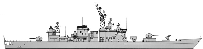
Conway’s profile – An HD profile is waited for 2027.
⚙ Hatakaze specifications |
|
| Displacement | 4,600/4,650 tons standard, 6,000/6,050 tons hull load |
| Dimensions | 150 x 16.4 x 4.8m (492 gt 2 in x 53 ft 10 in x 15 ft 9 in) |
| Propulsion | 2 shafts COGOG, RR Olympus + Spey SM1A: 72,000 hp (54000 Kw) |
| Speed | 30 knots (35 mph; 56 km/h) |
| Range | c6000 nm at 20 knots (11,200 km) |
| Armament | 2x 127mm/54 N°51, 2× 20 mm CIWS, 2×4 Harpoon SSM, SMI-1MR SAM(40), ASROC, 2×3 324 mm TTs |
| TDS | OYQ-4-1 CCS |
| Protection | NOLQ-1-3, OLR-9B ECM suites, 2x Mk 36 SRBOC decoy RL, SLQ-25 Nixie torpedo decoy |
| Sensors | OPS-28B, OPS-11C, SPS-52C, 2x SPG-51C, 2x FCS-2-21C, 2x Mk 90 radars, OQS-4 mod. 1 sonar |
| Air Group | Helideck only for a HSS-2B or SH-60J |
| Crew | 260 |
 JDS Hatakaze はたかぜ (DDG-171, 1984)


